
----- What is failure analysis
When clients come to us, they always ask questions like
In general, failure comes from
This is an elevator cable puller which failed at drive shaft due to poor engineering design.
Poor material may be caused by unqualified material or miss-used material. For like in the table, unqualified and qualified grey cast iron per ASTM A278 for Gray Iron Castings for Pressure-Containing Parts for Temperatures Up to 350oC
Carbon Manganese Phosphorus Sulphur Silicon
Section A 2.97 0.6 0.068 0.31 2.16
Typical Grey Cast Iron 2.5 / 4.0 0.2 / 1.0 0.002 / 1.0 0.02 / 0.25 1.0 / 3.0
Manufacturing also could cause the failure of product happen. Most common case happens in heat treatment product which heat treatment parameter will affect the microstructure of steel which will give different mechanic properties, like water quenched 1080 carbon steel is consist of martensite which has higher hardness but brittle than untreated 1080 carbon steel consisting of ferrite and pearlite
Most common failure caused by environment is corrosion like corrosion in pipeline, acid attack corrosion, degradation of concrete which cause loss of function. In pic shows a corrode brass pipe which cause leakage.
----- Failure Mechanism
Failure can occur by one or more of several mechanisms, including surface damage, elastic or plastic distortion and fracture. It's important to describe and categorize the following types of fracture by macroscopic scale which can lead to more comprehensive investigation of possible cause of failure including the environments, materials, manufacture procedure and operation procedure.
1. Ductile Fracture
Ductile fractures are characterized by tearing of material accompanied by appreciable gross plastic deformation and expenditure of considerable energy.
2. Brittle Fracture
Brittle fracture are characterized by rapid crack propagation with less expenditure of energy than with ductile fractures and without appreciable gross plastic deformation.
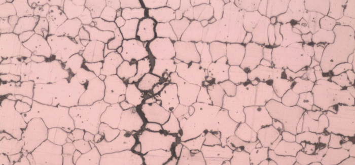
3. Fatigue Fracture
Fatigue fracture result from cyclic loading and appear brittle on a macroscopic scale. They are characterized by incremental propagation of cracks until the cross section has been reduced to where it can no longer support the maximum applied load, and fast fracture ensues. Frequently, the progress of a service-induced fatigue crack is indicated by a series of macroscopic crescents, or beach marks, progressing from the origin of the crack.
Fatigue feature of a truck spring
4. Environmentally Affected Fractures
Environmentally Affected Fracture is the fracture caused by a combination of several effects including wear failure, liquid-erosion failure, corrosion failure, stress-corrosion cracking, liquid-metal embrittlement, embrittlement by solid-metal environment, hydrogen-damage failure, corrosion-fatigue failures, elevated-temperature failures, failures in sour gas environment.
Stress-Corrosion Cracking on a water pipe
----- Failure analysis procedure
The level of failure cause/ factor can be list from top to bottom
We are always keeping open mind when doing failure analysis to avoid particular individual/group been blamed
For a complete evaluation, the sequence of stages in the investigation
and analysis of failure is as follows:
1. Collection of background data and selection of samples
2. Preliminary examination of the failed part (visual examination and record
keeping)
3. Nondestructive testing
4. Mechanical testing (including hardness and toughness testing)
5. Selection, identification, preservation and/or cleaning of specimens (and
comparison with parts that have not failed)
6. Macroscopic examination and analysis and photographic documentation
(fracture surfaces, secondary cracks, and other surface phenomena)
7. Microscopic examination and analysis (electron microscopy may be necessary)
8. Selection and preparation of metallographic sections
9. Examination and analysis of metallographic specimens
10. Determination of failure mechanism
11. Chemical analysis (bulk, local, surface corrosion products, deposits or
coatings, and microprobe analysis)
12. Analysis of fracture mechanics
13. Testing under simulated service conditions (special tests)
14. Analysis of all the evidence, formulation of conclusions, and writing the
report (including recommendations). Writing a report may not be necessary
in many product litigation cases; it is best to follow the advice of the
attorney or client with whom the analyst is working.
Report example
----- Modern analysis tools
Finite element analysis (FEA) is based on numerical computation that calculates all parameters and boundaries given. Supported with powerful computer processors and continuous software development, the finite element method is rapidly advancing. FEA can gives a more visual and detail investigation and description during failure analysis. Also it has great advantage in failure prediction and prevention by simulating the service environment. Commercial FEA softwares are equipped with wide range of objective functions,loading conditions, types of elements and multiple material structure.
Types of Engineering Analysis
Structural analysis consists of linear and non-linear models. Linear models use simple parameters and assume that the material is not plastically deformed. Non-linear models consist of stressing the material past its elastic capabilities.
Vibrational analysis is used to test a material against random vibrations, shock, and impact. Each of these incidences may act on the natural vibrational frequency of the material which, in turn, may cause resonance and subsequent failure.
Fatigue analysis helps designers to predict the life of a material or structure by showing the effects of cyclic loading on the specimen. Such analysis can show the areas where crack propagation is most likely to occur. Failure due to fatigue may also show the damage tolerance of the material.
Heat Transfer analysis models the conductivity or thermal fluid dynamics of the material or structure. This may consist of a steady-state or transient transfer. Steady-state transfer refers to constant thermoproperties in the material that yield linear heat diffusion.
When clients come to us, they always ask questions like
- Why this pipe leaking?
- Why these beams bend?
- Why these parts break?
- Why this unit is badly corroded?
- Why this unit is wear much faster than the others ?
- Is there any problem of materials or the treatment procedures that cause this accident?
- Are these problems of materials or the treatment procedures the major cause of this accident?
In general, failure comes from
- Deficient design
- Poor material
- Manufacturing
- Environment
This is an elevator cable puller which failed at drive shaft due to poor engineering design.
Poor material may be caused by unqualified material or miss-used material. For like in the table, unqualified and qualified grey cast iron per ASTM A278 for Gray Iron Castings for Pressure-Containing Parts for Temperatures Up to 350oC
Carbon Manganese Phosphorus Sulphur Silicon
Section A 2.97 0.6 0.068 0.31 2.16
Typical Grey Cast Iron 2.5 / 4.0 0.2 / 1.0 0.002 / 1.0 0.02 / 0.25 1.0 / 3.0
Manufacturing also could cause the failure of product happen. Most common case happens in heat treatment product which heat treatment parameter will affect the microstructure of steel which will give different mechanic properties, like water quenched 1080 carbon steel is consist of martensite which has higher hardness but brittle than untreated 1080 carbon steel consisting of ferrite and pearlite
Most common failure caused by environment is corrosion like corrosion in pipeline, acid attack corrosion, degradation of concrete which cause loss of function. In pic shows a corrode brass pipe which cause leakage.
----- Failure Mechanism
Failure can occur by one or more of several mechanisms, including surface damage, elastic or plastic distortion and fracture. It's important to describe and categorize the following types of fracture by macroscopic scale which can lead to more comprehensive investigation of possible cause of failure including the environments, materials, manufacture procedure and operation procedure.
1. Ductile Fracture
Ductile fractures are characterized by tearing of material accompanied by appreciable gross plastic deformation and expenditure of considerable energy.
2. Brittle Fracture
Brittle fracture are characterized by rapid crack propagation with less expenditure of energy than with ductile fractures and without appreciable gross plastic deformation.
3. Fatigue Fracture
Fatigue fracture result from cyclic loading and appear brittle on a macroscopic scale. They are characterized by incremental propagation of cracks until the cross section has been reduced to where it can no longer support the maximum applied load, and fast fracture ensues. Frequently, the progress of a service-induced fatigue crack is indicated by a series of macroscopic crescents, or beach marks, progressing from the origin of the crack.
Fatigue feature of a truck spring
4. Environmentally Affected Fractures
Environmentally Affected Fracture is the fracture caused by a combination of several effects including wear failure, liquid-erosion failure, corrosion failure, stress-corrosion cracking, liquid-metal embrittlement, embrittlement by solid-metal environment, hydrogen-damage failure, corrosion-fatigue failures, elevated-temperature failures, failures in sour gas environment.
Stress-Corrosion Cracking on a water pipe
----- Failure analysis procedure
The level of failure cause/ factor can be list from top to bottom
- Physical
- Human
- Latent
- Root
We are always keeping open mind when doing failure analysis to avoid particular individual/group been blamed
For a complete evaluation, the sequence of stages in the investigation
and analysis of failure is as follows:
1. Collection of background data and selection of samples
2. Preliminary examination of the failed part (visual examination and record
keeping)
3. Nondestructive testing
4. Mechanical testing (including hardness and toughness testing)
5. Selection, identification, preservation and/or cleaning of specimens (and
comparison with parts that have not failed)
6. Macroscopic examination and analysis and photographic documentation
(fracture surfaces, secondary cracks, and other surface phenomena)
7. Microscopic examination and analysis (electron microscopy may be necessary)
8. Selection and preparation of metallographic sections
9. Examination and analysis of metallographic specimens
10. Determination of failure mechanism
11. Chemical analysis (bulk, local, surface corrosion products, deposits or
coatings, and microprobe analysis)
12. Analysis of fracture mechanics
13. Testing under simulated service conditions (special tests)
14. Analysis of all the evidence, formulation of conclusions, and writing the
report (including recommendations). Writing a report may not be necessary
in many product litigation cases; it is best to follow the advice of the
attorney or client with whom the analyst is working.
Report example
----- Modern analysis tools
Finite element analysis (FEA) is based on numerical computation that calculates all parameters and boundaries given. Supported with powerful computer processors and continuous software development, the finite element method is rapidly advancing. FEA can gives a more visual and detail investigation and description during failure analysis. Also it has great advantage in failure prediction and prevention by simulating the service environment. Commercial FEA softwares are equipped with wide range of objective functions,loading conditions, types of elements and multiple material structure.
Types of Engineering Analysis
Structural analysis consists of linear and non-linear models. Linear models use simple parameters and assume that the material is not plastically deformed. Non-linear models consist of stressing the material past its elastic capabilities.
Vibrational analysis is used to test a material against random vibrations, shock, and impact. Each of these incidences may act on the natural vibrational frequency of the material which, in turn, may cause resonance and subsequent failure.
Fatigue analysis helps designers to predict the life of a material or structure by showing the effects of cyclic loading on the specimen. Such analysis can show the areas where crack propagation is most likely to occur. Failure due to fatigue may also show the damage tolerance of the material.
Heat Transfer analysis models the conductivity or thermal fluid dynamics of the material or structure. This may consist of a steady-state or transient transfer. Steady-state transfer refers to constant thermoproperties in the material that yield linear heat diffusion.